
Posted on May 11, 2005
Background
|
|
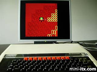
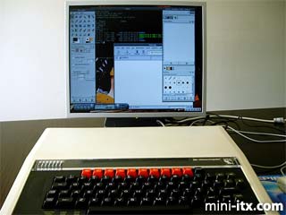
BBC ITX B running Linux and also Repton via an emulator
About a year ago I decided my aging Apricot P90 required an update but wanted something different from a bog standard desktop. A colleague at work mentioned the Mini-ITX web site where I came across Neil Jansen's project - "Commodore ITX-64". Of course, being an Acorn user in the past, I knew I had to retaliate. Ideally the project had to be based on the BBC model B, which every one remembers from school, and look as much like the original as possible. Could a Mini ITX board, hard drive and power supply fit into the case of a Beeb leaving all the external connectors? I was determined that the project should be stealth - just like the Commodore.
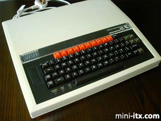
The Acorn BBC Model B (actually this is a B+ with 64K)
Hardware
The basis for the project was an old model B that had been partially stripped for parts. I ordered the new internals from the Mini-ITX online store - a 120W power supply kit, ME6000 board and 40GB hard drive. This would give me a fan-less design with enough power to allow me to connect an external DVD drive and floppy in the future.
I started by taking everything out, leaving just the case which was then cleaned up ready to be refitted. It took forever to figure out where to put everything. In the end the only way of fitting everything in was to try and fit the power supply where the old one was, the DC-DC converter on the far left of the main case area and the motherboard on the right with the connectors pointing to the left. The hard drive I could then mount above the power converter leaving space underneath for the connectors. I then had space down the back and front of the case for the original, external connectors.
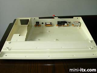
Empty case ready to be fitted up - attached along the back are
the original connectors re-soldered onto strip board.
External Connections
The original connectors at the back of the case were removed from the old motherboard and re-soldered onto strip board. PCB headers were then soldered in place so that the cabling from the motherboard connectors could be attached more easily. The finished sockets were then bolted onto the nylon spacers I'd glued to the bottom of the case. The old UHF output module (for connecting to the television) was also bolted in although it is not currently in use.
The original front sockets (located under the keyboard) are all IDE connectors. For the moment I decided not to use these so just cut the front off the old mother board and screwed it back into place. In the near future I plan to wire up the Tube port to an IDE DVD drive which I'll hide away inside an old 5.25" floppy drive.
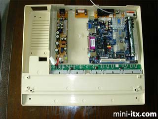
The DC-DC converter is mounted on the far left of the case. The Mini-ITX motherboard is screwed into place on the right hand side.
The output sockets are connected more or less according to their original function. The video out socket is connected to the RCA Video socket, the RGB is the VGA output, the RS422 is connected to the serial link and the Econet output is connected up to Ethernet. The analogue input is now used for the line out connection but the UHF output socket is currently unconnected. I have still got to connect the USB ports to either the cassette port output or the spare pins on the analogue in socket.
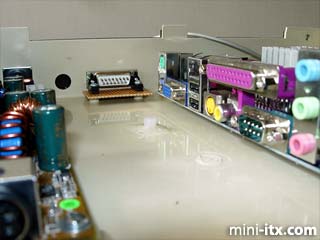
The layout leaves a nice gap for connecting cables to the Mini-ITX board.
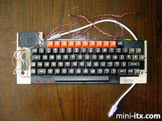
Keyboard
The keyboard was the most time consuming part of the project. I decided against a custom decoder like on the commodore because it would require EPROMS, etc. In the end I just used an existing keyboard controller wired into the B's own keyboard matrix. Anyone who has looked at the Beeb keyboard will know that some of the decoding and scanning circuitry is on the keyboard itself. First thing I did was take this off and cut the top right of the keyboard circuit board away. This prevented a useless bit of board sticking out into the case leaving more room for the motherboard and hard drive. I had to leave the top left of the circuit board alone because this is where the speaker is mounted. At this stage I also wired the BREAK key into the keyboard matrix. On the Beeb it's actually a separate switch connected to the reset line on the 6502 processor.
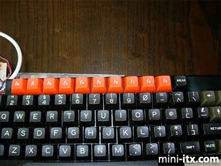
The top edge of the keyboard was cut away to
leave more room inside the case
I then took my donor PS2 Keyboard and mapped out which keys connected which pins together on the decoder chip. This gave me a map of rows and columns against keys. I then had to assign each full column to a column on the B's keyboard. Fortunately, the B has 8 rows, the same as the PS2 matrix although it only has 10 columns. Next I cut the PS2 circuit board down to make it small enough to fit where the expansion ROM would have gone on the left hand side of the keyboard. Wires were then soldered between the decoder and Beeb keyboard as per the mappings already made.
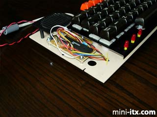
Keyboard controller was attached on the left hand side of the keyboard where the expansion ROM socket would have gone.
I then connected the keyboard to a normal PC and used showkeys to give me a keycode for each key pressed. A new keymap file was then created and hey-presto a fully functioning BBC keyboard driving a normal PC. The strange B keys, namely BREAK, Copy and shift lock were mapped to F11 (I'd assigned F0 to F10), Alt and Num lock respectively.
The keyboard on the Beeb also had the speaker and the cassette motor, caps lock and shift lock LEDs attached to it. I connected the caps lock and num lock LED outputs from the keyboard decoder to the caps lock and shift lock LEDs on the B keyboard. The cassette motor LED and speaker were wired with the appropriate sockets to match the HDD LED and PC speaker motherboard connector pins.
The finished keyboard with LEDs and speaker.
 |
 |
 |
Quick Links
Mailing Lists:
Mini-ITX Store
Projects:
Show Random
Accordion-ITX
Aircraft Carrier
Ambulator 1
AMD Case
Ammo Box
Ammo Tux
AmmoLAN
amPC
Animal SNES
Atari 800 ITX
Attache Server
Aunt Hagar's Mini-ITX
Bantam PC
BBC ITX B
Bender PC
Biscuit Tin PC
Blue Plate
BlueBox
BMW PC
Borg Appliance
Briefcase PC
Bubbacomp
C1541 Disk Drive
C64 @ 933MHz
CardboardCube
CAUV 2008
CBM ITX-64
Coelacanth-PC
Cool Cube
Deco Box
Devilcat
DOS Head Unit
Dreamcast PC
E.T.PC
Eden VAX
EdenStation IPX
Encyclomedia
Falcon-ITX
Florian
Frame
FS-RouterSwitch
G4 Cube PC
GasCan PC
Gingerbread
Gramaphone-ITX-HD
GTA-PC
Guitar PC
Guitar Workstation
Gumball PC
Hirschmann
HTPC
HTPC2
Humidor 64
Humidor CL
Humidor II
Humidor M
Humidor PC
Humidor V
I.C.E. Unit
i64XBOX
i-EPIA
iGrill
ITX Helmet
ITX TV
ITX-Laptop
Jeannie
Jukebox ITX
KiSA 444
K'nex ITX
Leela PC
Lego 0933 PC
Legobox
Log Cabin PC
Lunchbox PC
Mac-ITX
Manga Doll
Mantle Radio
Mediabox
Mega-ITX
Micro TV
Mini Falcon
Mini Mesh Box
Mini-Cluster
Mobile-BlackBox
Moo Cow Moo
Mr OMNI
NAS4Free
NESPC
OpenELEC
Osh Kosh
Pet ITX
Pictureframe PC
Playstation 2 PC
Playstation PC
Project NFF
PSU PC
Quiet Cubid
R2D2PC
Racing The Light
RadioSphere
Restomod TV
Robotica 2003
Rundfunker
SaturnPC
S-CUBE
SEGA-ITX
SpaceCase
SpacePanel
Spartan Bluebird
Spider Case
Supra-Server
Teddybear
Telefunken 2003
TERA-ITX
The Clock
ToAsTOr
Tortoise Beetle
Tux Server
Underwood No.5
Waffle Iron PC
Windows XP Box
Wraith SE/30
XBMC-ION